


As mentioned in the previous post written for Newtrace on Green hydrogen: A brief introduction to the hydrogen economy the capex cost of electrolyzers is very high (>$1500/kW) when compared to solar cells (>$300/kW) or batteries (>$150/kW).
24-57% of the total cost of an electrolyzer system can be associated with the high cost of raw materials and the manufacturing of stack components.
Commercially available electrolyzers are of two major types:
- Alkaline water electrolyzers (AWE)
- Proton exchange membrane electrolyzers (PEM)
Emerging technologies such as Anion exchange membrane electrolyzers (AEM) are similar to PEM in construction with the major difference being the membrane (and electrodes being similar to those used in AWE).
Another new electrolyzer system is Solid Oxide Electrolyzers which are based on a completely different stack technology.
In this post, we will explore the cost associated with the materials in the PEM electrolyzer and understand why the capex cost of such a system is so high.
Proton Exchange Membrane (PEM) Electrolyzers
The development of PEM water electrolysis started in the 1960s with the Gemini space program, but the decisive breakthrough came in the early 1970s with the developments by General Electric using DuPont's Nafion® membrane, which had been commercialized a few years earlier.
For the first 20 years, R&D efforts focused almost exclusively on military or aerospace applications, although General Electric also developed concepts for large-scale use.
However, a commercial breakthrough did not occur until the 2000s, when Proton OnSite placed its HyGen series on the market for industrial applications. Since then, a steady increase in commercial deployment by many companies has been observed over the last 20 years.
A PEM electrolyzer cell consists of a stack made of repeating cells that are electrically connected in series with the reactant water/product gas connected in parallel (Figure 1 & 2).
The numbers of cells in today’s PEM stacks ranges between 30-220 cells with an active area of up to 1,500 cm². Although the active cell area of a PEMEL stack is lower by a factor of 5 to 10, the gas production rate of a PEM stack is similar to an AWE stack with much larger cell areas, due to higher current density.
In general, PEM stacks have a more compact design, since the use of an ionomer as solid electrolyte and the arrangement of the electrodes on this ionomer/membrane effectively prevent mass transport limitation in a wide current density range.
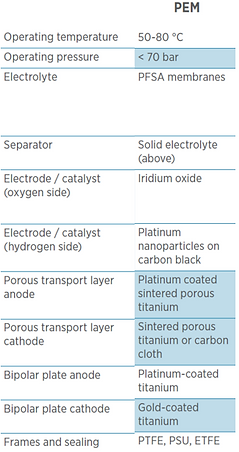
PEM electrolysis stacks are designed almost exclusively for operation under pressure. Typically, hydrogen is produced with 20-30 bars.
Most PEM electrolysis stacks have a rectangular shaped cell design and are operated at temperatures of 55 to 70 °C with current densities varying roughly between 1.5 – 2.5 A/cm².
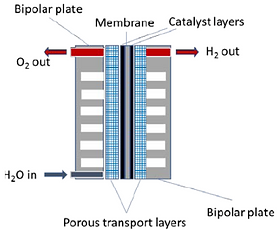
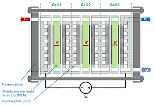
Fig 3 breaks down the materials used in the PEM electrolyzer.
The PEM cell consists of two half-cells where hydrogen and oxygen production occurs in distinct chambers (cathode and anode half-cells), which are separated from each other by the membrane.
The polymer membrane has the cathode and anode catalyst layers coated on the both sides to form what is called catalyst-coated membrane (CCM) or the membrane electrode assembly (MEA). Perfluorinated sulfonic acid (PFSA) membranes are usually used in PEM cells such as Nafion® from Chermours (formerly DuPont) or fumapem® from FuMA-Tech. Typically, these membranes have a thickness of 100-200 μm.
Next to a high proton-conductivity to minimize ionic resistance, the membranes also need to prevent a mixing of the product gases. However, during operation, permeation of oxygen and hydrogen through the membrane cannot be completely suppressed.
Especially during differential pressure operation with a several bar difference from the cathode to the anode, PFSA membranes exhibit relatively high gas permeability, which is much smaller than in an alkaline (AWE) cell, but nonetheless requires countermeasures.
The safety issue especially becomes important with thinner membranes and high differential pressures. In order to reduce the hydrogen crossover to the anode site, membranes with Pt nanoparticles as a recombination catalyst are applied.
Another challenge of PFSA membranes is their swelling behavior during water absorption. This leads to undesirable wrinkling, especially with large surface areas, and the membrane can be mechanically damaged in the compressed cell. This can be remedied by using internal fabric structures as reinforcement, which counteract the swelling but also reduce the conductivity. For these reasons, alternative ionomers are also being developed for PEM electrolysis, such as so-called hydrocarbon membranes. However, these materials have not yet been able to establish themselves technologically.
The anode and cathode electrocatalysts which are directly coated on the membrane, form the other part of the membrane electrode assembly (MEA). An efficient hydrogen production on the cathode requires platinum as a catalyst, usually supported on carbon for a more efficient material use. For oxygen production, the metals iridium (preferred), ruthenium, and their oxides are used.
Modern MEAs have a catalyst loading of about 2 mg/cm² on the anode side and about 1 mg/cm² on the cathode side. Currently, intense research and development focusses on the reduction of catalyst loadings for new MEA generations by approximately 40-60%.
Iridium in particular is a critical raw material and could be a bottleneck for a multi-GW electrolysis industry. The current global production capacity of Iridium is in the range of 9 tons per year. The catalyst layers on both the anode and the cathode are only a few micrometers thick.
Bipolar plates, as the name suggests, have a cathodic side and an anodic side. Their main function is to separate cells in the stack, and they have channels that facilitate the transport of water, hydrogen, and oxygen inside the stack. The bipolar plates in a stack must be made of corrosion-resistant materials such as titanium or coated steel. However, titanium is most commonly used in commercial products today. Titanium sheets with a thickness of up to 1 mm are used, which is preferably stamped out and the required channel and sealing structures are deep drawn or hydroformed.
On the hydrogen side, cheaper carbon composite materials can also be used, but this approach has not yet gained acceptance either, since the use of a single-layered titanium sheet as bipolar plate is more cost-effective.
The bipolar plates are therefore, usually die-stamped titanium plates which are then physico-chemically cleaned and then coated with either platinum or gold using physical vapor deposition techniques such as sputtering to enchance conductivity.
Between the MEA and the flow channels (flow field) of the bipolar plates (BBP), porous transport layers (PTL) are placed. The porous transport layer (PTL) is a layer that enhances water diffusion and water splitting reaction on the surface of the membrane in the electrolysis cells.
Although these PTLs are each only a few 100 μm thick, they ensure uniform distribution of the electric current between the bipolar plate and the electrodes. High electrical as well as thermal conductivity and gas and water permeability are the characteristics of a suitable PTL.
On the hydrogen side, the electrode potential is close to 0.0 VRHE, so the use of carbon paper or uncoated sintered porous titanium as a PTL is possible.
On the oxygen side, the use of carbon is not possible since the electrochemical oxidation of carbon occurs above a potential of 0.9 VRHE.
Therefore, titanium is almost exclusively used.
Titanium is characterized by its high conductivity and above all by its high corrosion resistance. Disadvantages are its high price, poor machinability, and the formation of titanium oxide on the surface on contact with oxygen at the anode side, which acts as a passivation layer providing electrical insulation and increasing the internal cell resistance. This problem is solved by using platinum-coated sintered porous titanium on the anode side.
Thick gold-coated stainless steel or titanium plates (called end plates) from both ends are added to structurally hold these cells inside the stack. The frame holding the stack is made up of thermoplastics such as PEEK or PPS-40GF.
As we can see, PEM electrolyzers use a lot of expensive and rare earth materials including platinum, iridium, gold and titanium. Furthermore, the cost of manufacturing some of these components such as the MEA, bipolar plates and PTL is very high, further adding to the cost of the electrolyzers.
This explains why PEM electrolyzers are so expensive when compared to other low-temperature electrolyzers such as AWE.
At Newtrace, we are further driving down the cost of electrolyzers by reducing the number of components from over 13 in PEM electrolyzers down to 4, as well as only using abundant earth metals and other low-cost materials instead of the expensive materials used in PEM electrolyzers.
Our unique technology allows us to reduce the capex cost by 3x compared to current PEM electrolyzer systems.
Newtrace is enabling wide-scale adoption of affordable green Hydrogen through their novel electrolyzer technology to help fight climate change and build a sustainable future for all. Follow us to stay informed about our updates!
About Author
