


When we talk about green Hydrogen production, the electrolyser is the point of focus, but often, the essential support system – Balance of Plant (BOP) is overlooked. This article will shed some light on the role of the BOP and how it effects the Hydrogen production in various ways. The basic role of the BOP can be itemized as below for several applications ranging across a wide range of Electrolyser systems:
- Supply Electrolyte to the Stack
- Power supply for the stack (which will be discussed in detail in upcoming articles)
- Separate gasses from the electrolyte
- Make-up the consumed water in the electrolysis process
- Recondition the electrolyte to meet the operating requirements of the Stack
- System safety
Sometimes this BOP is extended further to treat and compress the gas, often tailor made to meet the requirements of end user. For the same electrolyser, BOP designed by two different teams can have significant difference in the performance and efficiency of the whole system. Let’s look into the detail of how this BOP impacts the overall system performance.
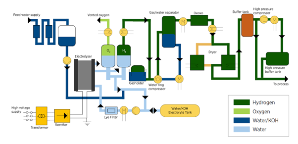
Pump is the common solution for supplying the electrolyte. Sometimes, the circulation pump is eliminated by employing a gravity tank to circulate the electrolyte. After the stack, pump is the highest energy consuming unit in the circulation system. This is why the piping network, component design and design selection will play a crucial role in the power consumption of BOP. The CAPEX & OPEX of pump and piping are inversely related to each other and the design can be targeted for only one factor at a time, at the expense of the other.
There are two streams outputted from the stack along with the electrolyte – Hydrogen& Oxygen gas. Both these streams are two-phase with the gas fraction varying from stack to stack depending upon the operating conditions. A gravity decanter or more commonly known as the Gas-Liquid separator carries out the task of separating these gases. This separator utilizes the natural phenomenon of Buoyancy - the tendency of lighter particles to float in fluids. Since the density difference between gases and liquids is huge, the separation is relatively easy. The separator provides enough residence time to the electrolyte for the submerged bubbles to reach the surface of liquid and escape into gas phase.
Although the separator is a simple passive tank, it dictates the amount of electrolyte holdup in the system and the electrolyte mist in the separated gas stream. Hence, it must be designed considering both the liquid and gas phases into consideration. Though most of the generated mist is recovered through mist eliminators in the separators, a fraction of the mist is carried over to the gas lines which must then be removed by scrubber. Further, part of the scrubbing liquid (make-up water quality along with the absorbed electrolyte mist) will be recycled back into the system as make-up. So, the mist generated can increase the load on the scrubber which can increase both CAPEX and OPEX. Under designing the liquid side could lead to the carrying over of gas bubbles back to the stack and then mix with generated gasses, ultimately taking a toll on the quality of gas.
Water maybe lost from the system in two different ways.
Hydrogen is produced through the splitting of a water molecule. 9kgs of water is consumed in order to produce 1kg of Hydrogen & 8kgs of Oxygen. Irrespective of the electrolyser type, this ratio stays fixed. Second are the evaporation losses, which vary from system to system as per the operating temperature and pressure. For a given set of operating conditions, evaporation losses will be proportional to the gas production rates. Though the evaporation losses cannot be eliminated, they can be recovered and then recycled back. All the water lost from the system needs to be compensated regularly to keep the system functional.
During electrolysis, only a part of the energy supplied to the stack is consumed for splitting the water molecule, the remaining quantity is converted to heat in several ways; predominantly by Ohmic and mass transport losses. This heat then gets accumulated in the electrolyte and raises the temperature of the whole system. The heat generated in the stack is constantly removed by cooling the electrolyte to the stack feed temperature through a heat exchanger. Most types of heat exchangers are suitable for this application; however, Plate type heat exchangers are often chosen due to their compactness and low cost. Although efficiency increases with temperature, the cost of the system also increases since maintaining this temperature requires withstanding construction materials and components.
Hydrogen gas flammability is not an unknown fact. As Hydrogen itself is the product, safety is a primary objective in the designing of BOP. Hydrogen has a flammability limit of 4% to 74% in air and 4% to 94% in Oxygen. Only 0.02 mJoules of energy is required to ignite Hydrogen, for comparison, walking on a carpet for a while can produce up to 25 mJoules!
Hence, operating with Hydrogen within these ranges is hazardous and should be avoided. The stack and the whole system are designed to operate outside of these flammability limits. Under steady state conditions, crossing these boundaries is highly unlikely. To avoid the operation from entering this range during the startup and shutdown time, a gas purging system is designed to push it into the safe zone. Nitrogen – a widely used and easily available inert gas is used inmost cases for the safe deployment of Hydrogen.
Apart from the performance aspects of the design, operator friendliness and the ease of maintenance should also be considered while designing the system. Ease of maintenance is defined by the down time utilized by the system due to a failure of components. Leakages due to piping & fitting issues are a frequent cause of failures. Though maintenance is an operational activity, the selection of components, the overall system layout design and the piping network play a crucial role in it. Making the system compact will reduce the CAPEX costs. If a system is being designed for 30 years of operation, it is important to consider these factors.
This concludes the basic functioning of the BOP. As mentioned earlier, a BOP can be designed for either low CAPEX or low OPEX. There are pros and cons for either use case depending upon the overall requirement.
Other integrations considered during the design include factors such as foot print, modularity, readiness to deploy, flexibility for expansion and integration with downstream. So far, most of the existing BOPs are created using the conventional design. However, there is space for creativity and for adopting alternative and innovative solutions.
If you have any crazy ideas for designing BOPs, be sure to let us know!
Newtrace is enabling wide-scale adoption of affordable green Hydrogen through their novel electrolyzer technology to help fight climate change and build a sustainable future for all. Follow us to stay informed about our updates!